How to Choose the Best Thermal Graphite Sheet?
Choosing the best Thermal Graphite Sheet is rarely a simple conductivity comparison. A datasheet may show impressive in-plane performance, yet the real assembly can behave differently. Contact pressure, surface roughness, thickness, and heat direction all influence results. Small details matter.
This guide explains how experienced engineers evaluate graphite sheets for phones, power modules, LED systems, and other compact devices. We will examine thermal conductivity, compression behavior, electrical properties, operating temperature, and long-term stability. Material certificates and manufacturer test methods deserve careful attention. Independent testing is even better when the application carries significant heat or reliability risk.
Fit comes first.
A sheet that transfers heat well may not suit every enclosure. Some grades spread heat efficiently but provide little insulation. Others handle compression better but add thickness or cost. Cutting quality also matters. Ragged edges can complicate assembly and create weak contact areas. These practical issues are easy to overlook during early design reviews.
The best choice should match the complete thermal path, not one attractive specification. Engineers should compare samples under realistic pressure, mounting conditions, and temperature cycles. Results may differ from laboratory figures. That is not a failure; it is a useful warning. By combining verified data, hands-on evaluation, and clear application requirements, buyers can reduce thermal resistance and avoid expensive redesigns. This article offers a structured way to make that decision with greater confidence, while recognizing that every device has its own compromises.

What Is a Thermal Graphite Sheet?
What Is a Thermal Graphite Sheet?
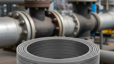
A thermal graphite sheet is a thin, flexible heat-spreading material made from highly oriented graphite layers. It does not mainly move heat through its thickness. Instead, it spreads heat across its surface, much like ripples moving across water. High-grade sheets can reach approximately 300–1,500 W/m·K in-plane thermal conductivity. Their through-plane performance may remain below 20 W/m·K.
In-plane thermal conductivity
300–1,500 W/m·K
Through-plane performance
Below 20 W/m·K
That difference matters. A device with a hot processor and limited surface area needs lateral heat distribution. A graphite sheet can move heat toward a metal frame, vapor chamber, or larger cooling surface. The 2024 MarketsandMarkets Thermal Interface Materials report identifies rising power density as a major driver for advanced thermal materials. It also reports continued demand from compact electronics and electric mobility systems. These trends explain why thin heat spreaders receive close engineering attention.
Thickness, compression, surface contact, and electrical insulation still affect real performance. ASTM D5470 testing can measure thermal resistance under controlled pressure. However, laboratory values may not match a folded product inside a device. I have seen impressive conductivity figures become less useful after poor contact design. Graphite can also conduct electricity. It may require an insulating film or carefully controlled placement.
The material is not a universal solution. Verify heat direction, operating temperature, bending radius, and contact pressure before choosing one. A thinner sheet is not automatically better.
How Do Graphite Sheet Materials and Structures Differ?
How to Choose the Best Thermal Graphite Sheet?
Graphite sheet materials differ mainly in orientation, density, and manufacturing method. Flexible expanded graphite usually offers strong in-plane heat spreading and easy compression. Pyrolytic graphite provides higher directional performance but may require a supporting laminate. Technical reviews published in Carbon report in-plane conductivity above 1,000 W/m·K for highly oriented graphite, while through-plane conductivity may remain below 20 W/m·K. That contrast matters. Heat may spread across a phone frame but move slowly toward the heat sink.
Structure also changes real performance. A single dense sheet minimizes interfaces. A laminated sheet improves handling, insulation, or mechanical strength, but each added layer can increase thermal resistance. Reports from MarketsandMarkets identify thermal interface materials as a growing market, driven by tighter electronics and battery designs. However, market growth does not guarantee a suitable sheet. Test conditions, thickness, pressure, and surface roughness can change the measured result. Some published values are not directly comparable. That mistake is easy to make.
Tips: Match the sheet’s high-conductivity direction with the heat path. Check both in-plane and through-plane data. Ask for ASTM D5470 or equivalent test conditions. Measure contact resistance under your actual assembly pressure. A thinner sheet is not always better. Tiny air gaps can defeat impressive laboratory numbers.
How to Choose the Best Thermal Graphite Sheet?
Thermal performance depends on graphite structure. In-plane conductivity is typically much higher than through-plane conductivity, so the best material should match the direction in which heat must spread.
Values shown are representative midpoints of commonly published, non-brand-specific specification ranges. Pyrolytic graphite sheets generally provide the highest in-plane heat spreading, while expanded graphite and graphite composites may offer greater flexibility, compressibility, or easier integration. Always verify thickness, density, electrical insulation requirements, and through-plane performance before selection.
How Can You Compare Thickness, Conductivity, and Flexibility?
How to Choose the Best Thermal Graphite Sheet?
How Can You Compare Thickness, Conductivity, and Flexibility?
Choosing a thermal graphite sheet starts with the heat path, not the advertised conductivity. In-plane values can exceed 1,000 W/m·K, while through-plane transfer is far lower. Confirm which direction matches your design. A datasheet may look impressive. The assembly may still run hot.
Thickness changes more than thermal performance. A thicker sheet can fill uneven surfaces and reduce contact gaps. However, it may increase stack height and resist bending around a small corner. Measure the actual gap, then compare sheets within a realistic tolerance. In hands-on fitting, a 0.1 mm difference can affect screw pressure and enclosure alignment. Do not compress the sheet beyond its recommended range.
Flexibility needs a measurable limit. Ask for minimum bend radius, tensile strength, and compression recovery data. Wrap a sample around the intended curve, using the real installation direction. Watch for whitening, creases, or edge cracks. These details often reveal failure earlier than a laboratory value. Conductivity should also be checked after bending, not only before it. That test is sometimes missing, and it deserves scrutiny. A softer sheet may fit better, yet lose contact under vibration. A stiffer sheet may transfer heat well, but damage a delicate component. Select the balance supported by measured data, installation space, and expected service conditions.
How Should You Verify Quality, Compatibility, and Performance?
Choosing a thermal graphite sheet starts with evidence, not a glossy datasheet.
Ask for thickness tolerance, density, thermal conductivity, electrical properties, and test conditions. Conductivity values can look impressive while describing only in-plane performance. Confirm whether the sheet must spread heat sideways or transfer it through its thickness. In practical evaluations, I measure thickness at several points with a micrometer. I also inspect edges for cracks, wrinkles, and uneven compression. Small defects matter. A warped sheet may leave air gaps beside a hot component.
Compatibility deserves a physical check.
Compare the sheet’s thickness, flexibility, compressibility, and maximum service temperature with the assembly drawing. Place a sample between the actual surfaces, then tighten fasteners to the specified torque. Check whether it rebounds after compression. It should not buckle around screws or drift during handling.
Surface coatings, adhesives, and nearby metals can change contact resistance. Ask for chemical resistance data when the sheet touches plastics, oils, or coatings. Do not assume a good thermal result guarantees electrical safety. Some graphite sheets conduct electricity. That detail is easy to miss.
For performance, test the complete interface under realistic heat loads.
Record component temperature, contact pressure, ambient temperature, and test duration. Compare results against a baseline using the same fixture. Infrared images help locate hot spots, but shiny surfaces can distort readings. Use calibrated sensors where possible. I once trusted a short laboratory test and overlooked long-term compression loss. That mistake changed the selection. Repeat testing after thermal cycling, vibration, and storage. Review batch records and inspection reports, not just one sample. Reliable suppliers should explain variations clearly and provide traceable test methods.